The LHPOST6 is the largest shake table facility in the U.S. and the second largest in the world. It enables ground-breaking experimental research related to structural, geo-structural, soil-foundation-structural, and non-structural components and systems including how these systems behave during realistic multi-component earthquake excitations, and how they should be conceived and designed to resist such excitations best.
LHPOST6 System & Components
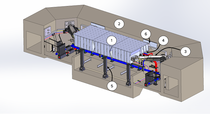
- Component 1 is the 12.2 m long by 7.6 m wide by 2.2 m deep honeycomb steel platen with a grid of multi-purpose, high-capacity, tie-down points spaced at 610 mm o.c.
- Component 2 is the reinforced concrete reaction mass and the service tunnel that connects to the Hydraulic Power System Building. The reaction mass also has a grid of multi-purpose, high-capacity vertical tie-downs for the deployment of safety or measurement frames or for the deployment of reaction frames as needed for hybrid testing.
- Component 3 consists of the set of four ±750 mm stroke servo-controlled dynamic horizontal (longitudinal) actuators mounted in a V-shape configuration each with a force capacity of 2.7 MN in tension and 4.2 MN in compression. Each actuator is equipped with two four-stage servo-valves (each rated for a flow of 10,000 liter/min @ 7 MPa pressure drop).
- Component 4 comprises the six vertical actuators, each equipped with a high-flow and high-speed servovalve (rated for a flow of 10,000 liter/min @ 7 MPa pressure drop), which support the shake table platen and provide vertical, roll, and pitch motion capability.
- Component 5 is a set of three nitrogen-filled hold-down struts that passively pre-compress the platen against the sliding bearings and, consequently, provide overturning moment resistance.
- Component 6 is a crash protection system as a third line of defense in the case of an uncontrolled motion condition.
- Component 7 (not shown) is a weatherproofing system consisting of removable concrete planks, removable composite concrete-steel planks, and steel cover plates for protection against falling debris.
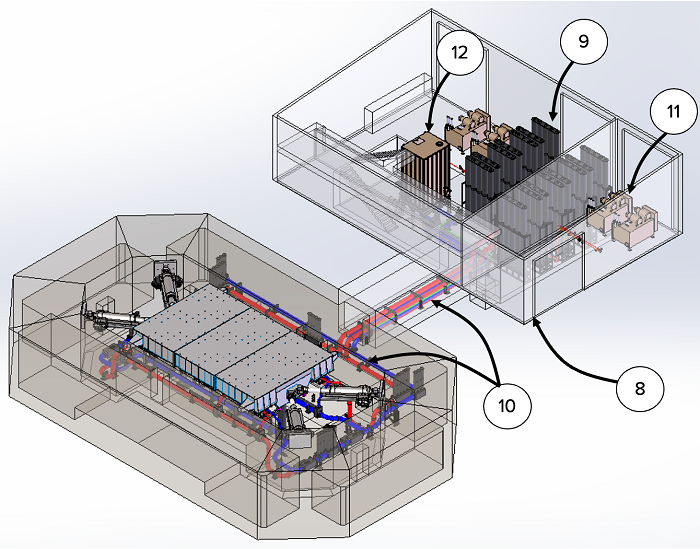
- Component 8 is the hydraulic power supply building and tunnel.
- Component 9 is a 36.9 m3 (9,750 gallon) accumulator bank consisting of 75 bottles at 0.38 m3 (130 gallon) each, which can provide approximately 9.0 m3 (2,300 gallons) of oil at 20.7 MPa (3,000 psi). The accumulator bank is equipped with six blow-down valves (manifolds) which convert the high-pressure oil from the accumulators (between 21 and 35 MPa) to a system pressure output of 21 MPa (3,000 psi) for supplying the system actuators.
- Component 10 is two 0.3 m (12 in) diameter pressure lines (red colored piping in the figure images) transport the high-pressure oil from the hydraulic power supply building to the entrance in the reaction mass and feed a “pressure” ring main (0.3 m diameter single steel pipe) that feeds the servo valves of all the horizontal and vertical actuators. The return flow from all the horizontal and vertical actuators is directed to the surge tank through a “return” ring main (blue colored piping in the figure images) that goes around reaction mass and through two 0.3 m (12 in) diameter steel tubes through the tunnel to the surge tank.
- Component 11 is one 720 liter/min at 21 MPa (190 gpm at 3,000 psi) pump that provides pilot flow to the servo valves of all actuators for servo-control and three 430 liter/min at 35 MPa (114 gpm at 5,000 psi) pumps to pressurize (charge) the accumulator banks before and during a shake table test.
- Component 12 is a surge tank with a capacity of 20 m3 or 5,280 gallon that collects return flow oil.
Basis of Design
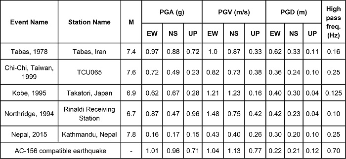
The design of the LHPOST6 was developed in a collaborative effort between UC San Diego and MTS Systems Corporation. The target performance of the LHPOST6 was defined through its ability to reproduce the six tri-axial strong ground motions defined in Table 1 below. These ground motions are from the 1978 Tabas (Iran), 1994 Northridge (California), 1995 Kobe (Japan), 1999 Chi-Chi (Taiwan), and 2015 Nepal earthquakes, and an AC- 156 compatible artificial earthquake record developed for seismic qualification testing (ICC Evaluation Services Inc., 2007).
Table 1: Tri-axial strong ground motion records considered for the preliminary design of LHPOST6.
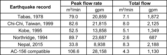
To achieve the desired design criterion, the hydraulic power system was designed using inverse simulation, which takes a target tri-axial ground motion record as input and computes the system demands in terms of displacement, velocity, acceleration, force, servovalve opening, oil flow and pressure. The peak demand flow rate and total demand flow required to reproduce the six considered tri-axial earthquake records are shown in Table 2 below. It is observed that the Chi-Chi and Nepal earthquake records require a total flow demand exceeding 8.0 m3 (2,100 gallons), dictating the need for a 36.9 m3 (9,750 gallon) accumulator bank (75 bottles of 0.38 m3 (130 gallon) each) which can provide approximately 9.0 m3 (2,300 gallons) of oil at 20.7 MPa (3,000 psi).
Table 2: Peak demand flow rate and total demand flow required to reproduce the tri-axial strong ground motion records defined in Table 1; bare table condition.
Acceptance Test Results
For the three components of the 1995 Kobe earthquake record that was used in the Basis of Design, Figure 1 shows the target vs. achieved translational acceleration time histories, Figure 2 shows the target vs. achieved translational velocity time histories, and Figure 3 shows the target and achieved translational displacement time histories. A comparison between target and achieved five-percent damped tri-partite (displacement/pseudo-velocity/pseudo-acceleration) linear elastic response spectra is provided in Figure 4.
The fidelity of the responses are strong, and similar levels of signal tracking fidelity were observed for the other tri-axial earthquake records considered in the LHPOST6 design. The level of fidelity in signal reproduction for the vertical component and other motion components will be further improved through experience gained as we implement advanced control capabilities that are built into the MTS 469D shake table controller such as Adaptive Inverse Control (AIC), On- Line Iteration (OLI) and Specimen Dynamics Compensation (SDC).
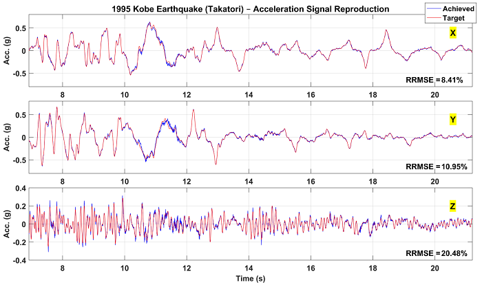
Figure 1: Comparison of target and achieved tri-axial acceleration time histories for the 1995 Kobe earthquake record (see Table 1 in Basis of Design).
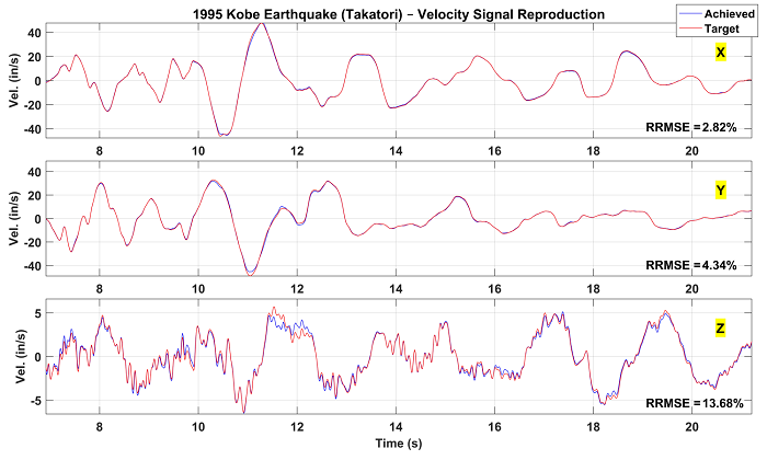
Figure 2: Comparison of target and achieved tri-axial velocity time histories for the 1995 Kobe earthquake record (see Table 1 in Basis of Design).
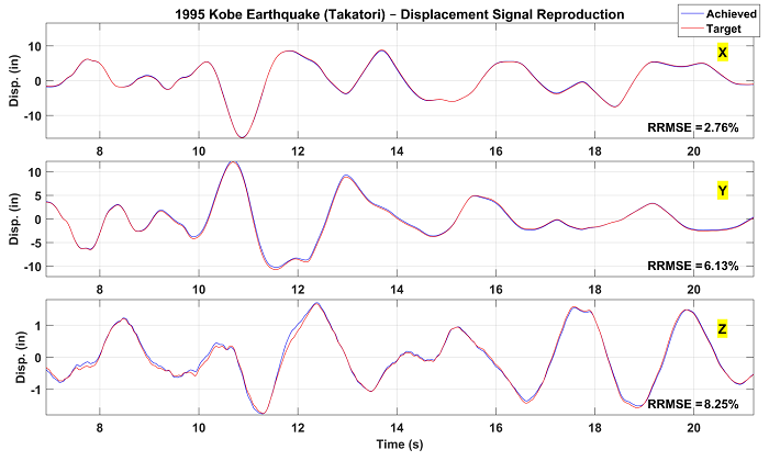
Figure 3: Comparison of target and achieved tri-axial displacement time histories for the 1995 Kobe earthquake record (see Table 1 in Basis of Design).
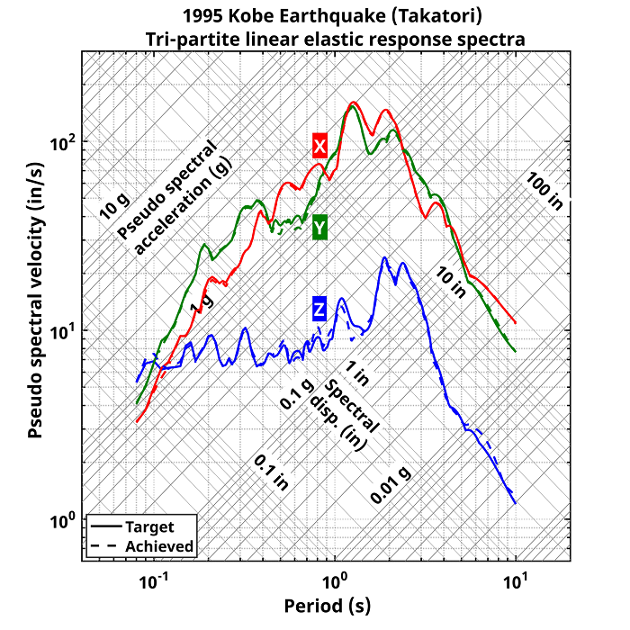
Figure 4: Comparison of the target and achieved 5% damped tri-partite linear elastic response spectra for the 1995 Kobe earthquake record (see Table 1 in Basis of Design).